Introduction
Device tool application is designed for configuration and diagnostics of IOFireBug line of devices. It connects IOFireBug Engine with computer and allows complete configuration and control – Wagon expanders, communication parameters, signal processing etc.
IOFireBug Engine connection
IOFireBug Engine is equipped with FTDI chip, which means it appears as generic serial port device (COM). Make note of COM port number, it will be needed later.
Application startup and communication configuration
Thanks to Device tool it is possible to determine status of IOFireBug devices connected to computer.
On the left side, there is a list of IOFireBug Engine devices, witch device tool will be trying connect to. (Possible IOFireBug Engine expanders configurations are described in Technical product description document). Using Add new, Remove and Remove All buttons it is possible to manage IOFireBug Engine devices.
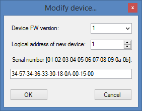
When adding new device, application asks for device FW version, link adress and product serial number. FW version and serial number are written on device itself, link adress depends on DIP switch position, for more details on how to adress a device, refer to Technical product description document.
After new device is set up, choose COM port and baundrate from dropdown list. IOFireBug Engine default baundrate is 115200.

If everything goes smoothly, after opening connection with “Open” button, selected device turns green (address: 1), where 1 is DIP switch adress, and Communication status changes to ONLINE.
If we want to switch between devices, just select one from list.
In the middle section configuration controls can be found.
Device control and info tab
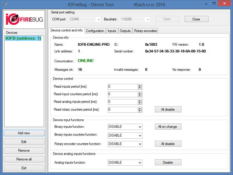
Name, ID and Firmware version are stored on IOFireBug engine device, and are shown in device info section upon successful connection. Link adress shows DIP switch state. “Messages ok” counts successfully transmitted messages, “Invalid messages” counts received messages, which are in some way incorrect. “No response” counts messages, which had no response. Last two can happen for example when device is unexpectedly disconnected.
Device control contains parameters for IOFireBug library, ergo PC side settings (in this instance Device tool).
Device input functions and Device analog input functions are parameters, which are on IOFireBug Engine device side.
Device control options set interval in which the computer queries the device for IO change. Values are in millisecond.
Binary inputs function, Binary inputs counters function and Rotary encoder counters function can be set, whether we wanted to be notified about any change (on change) or select one of the predefined periods (i.e. ON_PER_100MS). From this moment on, the device send messages without the need for PC to query. This setting can be changed at any time, and even turned on or off on all functions at the same time, using buttons “All on change” or “All disable”.
Device analog inputs functions features the same settings, but without the option to send on change.
Configuration tab
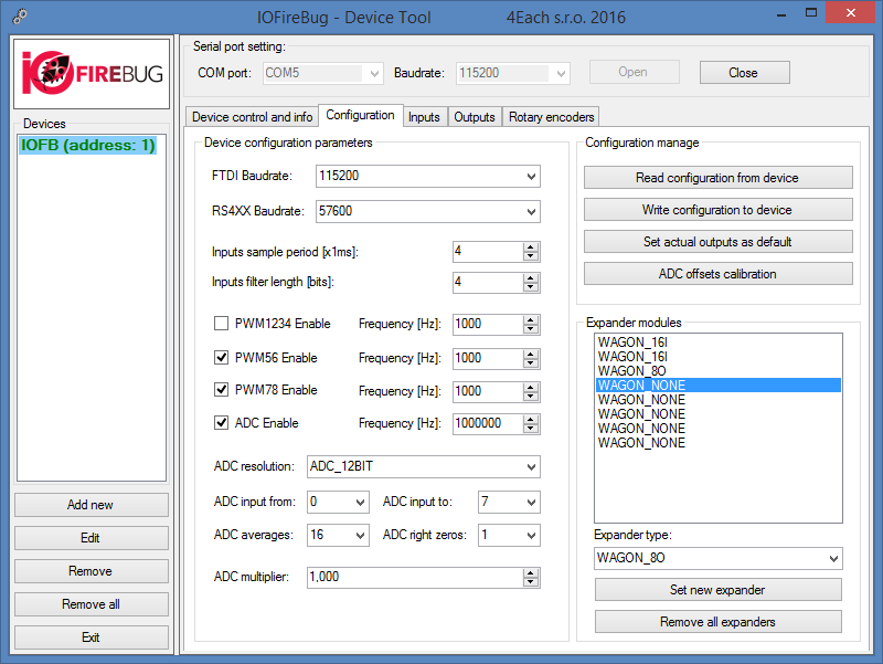
Configuration tab is where entire IOFireBug device configuration takes place.
Communication
FTDI baundrate sets communication speed.
RS4XX Baundrate is second serial interface channel, which can be used in the same manner as USB. Options for RS-485 or RS-422 connection are described in Technical product description document.
Binary inputs
Inputs sample period is parameter in milliseconds, which determines how often IOFireBug samples all inputs. Related parameter is Inputs filter length period in bytes.
This function describes following example:
Input sample period is set 2 and Filter length 4.
IOFireBug engine samples input states every two milliseconds and stores these samples to 4 bits long array. If all 4 samples are the same, this value is assumed to be the correct value. Thank to this filter, we can define, how small change the device will register. I.e. fluctuations are filtered on IOFireBug Engine device side, without the need of dealing with this on SW side on PC.
Binary outputs
Pulse width modulation (PWM) configuration
Using PWM1234 Enable checkbox, PWM will be enabled on first four outputs 1-4. Next working frequency can be set. Maximum value is 20 000 Hz and minimal is 1 Hz. In the same way can be set PWM on outputs 5 and 6 (PWM56 Enable), 7 and 8 (PWM78 Enable). These three groups can be independently controlled; however, each individual output cannot bet set.
Set actual outputs as default button sets default settings upon start up. This topic will be described in more detail in following chapter.
Analog inputs
Analog inputs sampling I set by ADC Enable (Analog Digital Converter) checkbox. Maximal frequency of AD converter is 1 400 000 Hz. This is the speed of converter, not sample rate. Sample rate can be calculated by dividing converter speed by number of resolution bits or number of active analog inputs. Sample rate resolution can be changed by option “ADC resolution“, values are 8 or 12 bits.
“ADC input from“ and “ADC input to“ sets, which analog inputs are being used.
IOFireBug Engine supports sample averaging (ADC averages) and trim lowest priority bits (ADC right zones). Thanks to this functionality, IOFireBug Engine can filter signals by itself (sacrificing accuracy).
ADC multiplier can be assigned to any real number and is used to multiply all analog input values. This can be useful for unit conversion on IOFireBug Engine side, without PC intervention.
For accurate analog voltage measurement, it is needed to calibrate inputs. This can be done by executing “ADC offsets calibration” function. Analog inputs have to be connected to target of measurement, which is in LOW state (in best case scenario 0V – GND). In this state, execute calibration. IOFireBug Engine automatically sets zero value to measured voltage. This stabilizes measured values.
Expanders configuration
Configuration of expanding modules is done by “Expander modules“ list. This configuration defines, which expanders are connected (using SPI interface), and thus how should IOFireBug Engine communicate. Maximum of 8 expanders can be connected. Each expander has to chained behind the last, so it is not possible to select type “WAGON_NONE” between expanders.
Current firmware supports following types of expanders:
| Type | Description |
| WAGON_NONE | Slot is not used |
| WAGON_16 | Slot is used by Wagon 16I |
| WAGON_8O | Slot is used by Wagon 8O |
| WAGON_8RELAY | Slot is used by 8 relay module for high current switching [prototype] |
| WAGON_16IO | Slot is used by 16 GPIO module [prototype] |
“Remove all expanders” function – as name suggest, this removes all expanders at once.
For configuration new expander, first is essential to select correct position, then choose expander type from dropdown list. Selecting new expander is done by clicking “Set new expander” button. However, this does not send data to device, only saves selection for user to be able to set other expanders.
After all expanders are set, use “Write config” button to send data to device.
Inputs tab
In “Binary inputs” column, there are displayed device inputs states, indexed 0 to 7, providing that inputs are correctly configured (refer Device control and info chapter).
In Binary inputs list, each input activates checkbox depending on its logical value. In right column there are input counters „In counter“. These values increment by one on every rising and falling edge. For input counters to work, “Read input counters period” value must be set on Device control and info tab. “Clear counters” function is used to reset all counters.
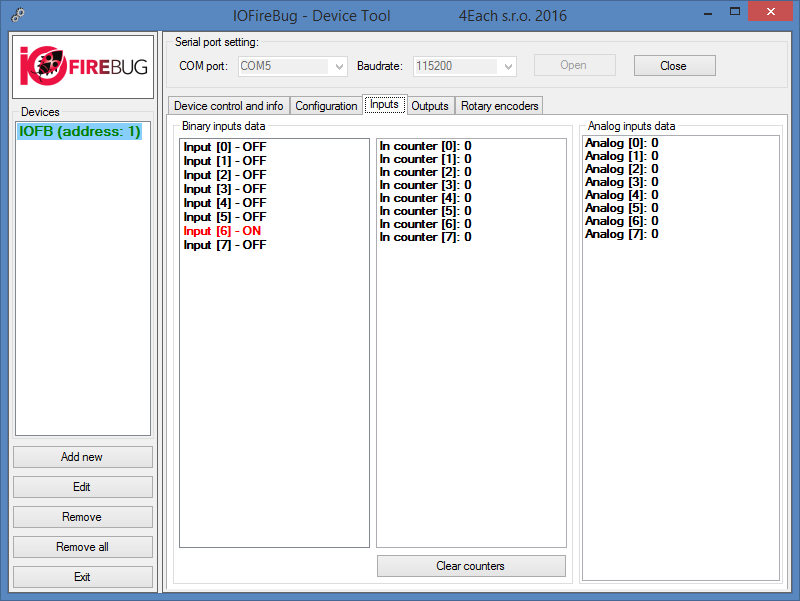
Sloupec „Analog inputs data“ zobrazuje data z AD převodníku. Pokud zapneme AD převodník na všech vstupech (záložka Configuration) a zároveň jsme aktivovali vyčítání analogových vstupů (na záložce Device control and info), můžeme sledovat měřené hodnoty. Pro rozlišení 12 bitů se hodnoty budou pohybovat od 0 do 4096. V tento okamžik je vhodné konfigurovat filtraci analogových dat na záložce Configuration.
“Analog inputs data” column shows data from AD converter. If ADC I turned on all inputs, (refer configuration tab) and periodic analog reading is enabled (Device control and info tab), we can observer measured values. For 12bit resolution, values may vary between 0 and 4096. In this instance it is configure analog inputs filtration (Configuration tab).
Outputs tab
In Outputs tab, we can set each output individually, either in logical (HIGH/LOW) values, or utilize pulse width modulation.
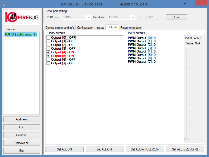
Binary outputs control using logical values
For binary output control, it is possible in Binary outputs list to check corresponding checkbox. This sends data to IOFireBug Engine device and switches logical value of physical output. This procedure holds true, if PWM function is not enabled (Configuration tab).
Binary outputs control using PWM
Before using PWM, make sure it is enabled in Configuration tab for desired output, and configuration is written to the device. PWM value is set by sliding control on the right hand side (values between 0 and 255).
Every output has its own status LED, to confirm sent commands.
Rotary encoders tab
Last tab is designated for use with specific signal processing on binary inputs used with rotational encoders or incremental sensors. These types of sensors use two binary inputs, and assumes that its combination makes possible for determination of directional movement. This is achieved by 90° phase shift. IOFireBug Engine firmware determines rotation direction and increases or decreases rotary counter value accordingly. Rotational counter is 16bit number, and it overflows when reached its border values.
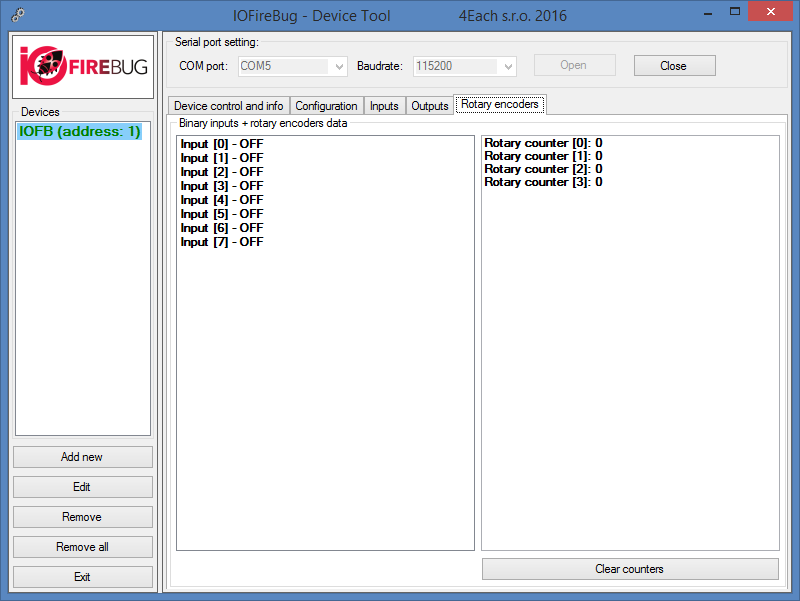
In Rotary encoders tab, on left hand side, is shown list of binary outputs identical with Inputs tab list. In second column rotary counters are located. As mentioned above, rotary encoders use two pins, so there are only four encoders. Rotary encoder 0 uses pin 1 and 2. To turn on counting, in “Device control and info” tab, set “Read rotary counters period”. To reset counter, press “Clear counters”.