IOFireBug Engine
Product overview
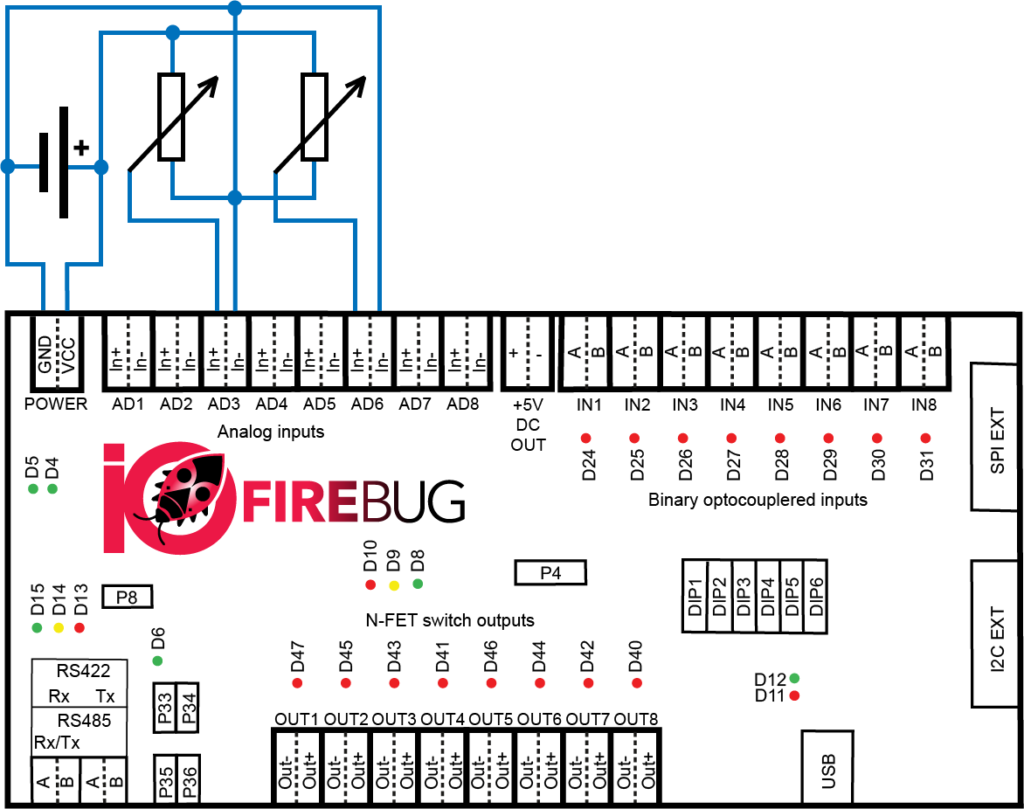
IOFireBug Engine block diagram in shown on following image. Device is equipped with following interfaces:
- 8x analog input
- 8x binary input (galvanically isolated)
- 8x switching N-FET output (galvanically isolated, all channels have common ground)
- RS485 / RS422 Interface (switchable, galvanically isolated)
- USB to Serial Interface (FTDI)
- SPI Interface for optional expanders
- I2C Intentionally unused
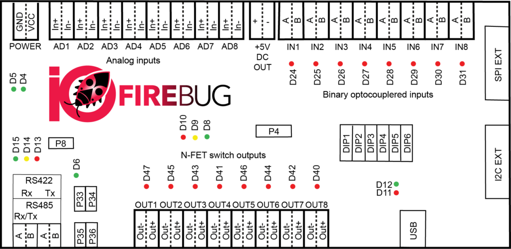
IOFireBug Engine block diagram
Power supply
Device can be powered using DC power supply, using 10V to 30V.
Power LED indication:
| LED | D5 | D4 | D6 |
| Meaning | Voltage present 3,3V from power supply | Voltage present 5,0V from power supply | Voltage present
5,0V from galvanically isolated power supply |
| Color | Green | Green | Green |
If everything is ok, all three LED shine continuously.
DIP switch
DIP3 to DIP6 sets communication binary address, from 0 to 31. Address 0 is not used and device doesn’t respond to it.
| Switch | DIP1 | DIP2 | DIP3 | DIP4 | DIP5 | DIP6 |
| Meaning | Device logical address MSB=DIP3 and LSB=DIP6 | |||||
Device default values
If you set all DIP switches to position log1 and reboot the device (cut off power supply), the unit clears the last configuration of EEPROM memory, this sets the default values. The unit indicates memory erase by flashing red LED D10. To return back to normal operational state, you need to switch all DIP switches down and restart unit.
In default state, the unit is set with following communication speeds:
| Line | USB | RS485/422 |
| Default communication speed [Baud] | 115200 | 57600 |
Selecting RS485/422 mode
Using jumper on P8 port, RS485 mode is activated. Communication takes place on P6 connector (RxTx A + B). If jumper is not present, line is in RS422 mode. Communication takes place on P6 (Rx A + B) and P7 (Tx A + B) connector.
Communication status LED:
| LED | D15 | D14 | D13 |
| Meaning | TxD (unit is sending data) | DIR (line direction change in RS485 mode – LED shining = sending) | RxD (unit is receiving data) |
| Color | Green | Yellow | Red |
RS485 line termination:
Using jumper on P33 and P34 port terminates the RS485 line.
RS422 line termination:
Using jumper on P33 and P34, P35 and P36 port terminates the RS422 line.
USB to computer interface
The device is equipped with a USB to UART converter from FTDI manufacturer. After connecting the device to a computer, all the necessary drivers are installed, and new virtual serial port (COM) is created. With it you can communicate with the device according to the attached communication protocol.
Communication status LED:
| LED | D12 | D11 |
| Meaning | TxD (unit is sending data) | RxD (unit is receiving data) |
| Color | Green | Red |
Binary input connection
Binary inputs are galvanically isolated using opto isolators and independent of input voltage. Input voltage range is from 10V to 30V. Every input has its own indication LED, which is lid on as output is in HIGH state.
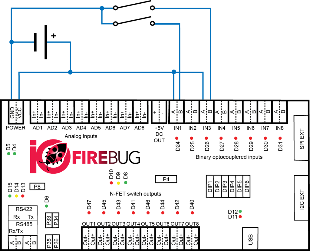
Binary input wiring example
Binary output connection
The binary outputs consist of N-FET switching transistor. Load switching is realized by grounding (connecting negative wire). The transistor output is rated for switching 3A of continuous current, in short-term can switch up to 4A. Maximum switching voltage is 50V. Each output has a LED indicator that shines red when the transistor (output) is closed.
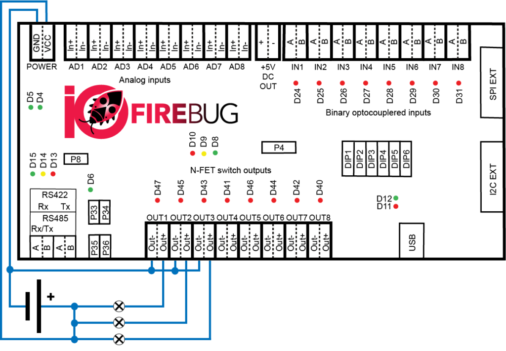
Binary N-FET output wiring example
Analog input connection
Analog inputs are used to precisely determine input voltage.
Analog input wiring example
Wagon expansion modules
Modules are connected to the IOFireBug Engine device with 10 pin ribbon cable, using SPI interface. When using extension modules, IOFireBug Engine must be properly configured. Expansion modules can be connected in chain in any order. The last module must be terminated by jumper. The Engine can use a maximum of 8 expansion modules at once.
Wagon 16I expansion module
Expansion Module allows you to connect additional 16 digital inputs to the IOFireBug Engine. Inputs are electrically identical to those on the Engine device. Connection circuitry is therefore analogous. If module is last in the chain, bus must be terminated by P5 jumper.
The module is powered by the Engine device. Each input has its own LED that shines red when the input is in HIGH state.
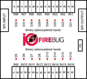
Binary input expander
Wagon 8O expansion module
Expansion Module allows you to connect additional 8 binary outputs (N-FET) to the IOFireBug Engine. Outputs are electrically identical to those on the Engine device. Connection circuitry is therefore analogous. If module is last in the chain, bus must be terminated by P4 jumper.
By default, the module is powered by the Engine device, but it may also be powered from an external power supply. To select how the module is powered, use jumper P3. When the module is powered correctly, green LED D1 shines. Each output has its own LED that shines red when the output is in HIGH state.
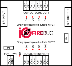
Binary N-FET output expander
Multiple IOFireBug Engine devices setup
For large applications, multiple IOFireBug Engine devices can be used, interconnected with serial interface. For this purpose, IOFireBug Engine has one serial interface, which can be switched to one of the following modes:
- RS-485 (multipoint)
- RS-422 (point-to-point)
RS-485 interface
RS-485 interface allows connection of up to eight IOFireBug Engine sets (depending on the configuration and the required amount of data). RS-485 has only a half-duplex communication, and it is always necessary to assess the suitability of its use in a given application.
Option number one is to use RS-485 as USB convertor or RS-485 expansion card for PC. This solution requires third-party products.
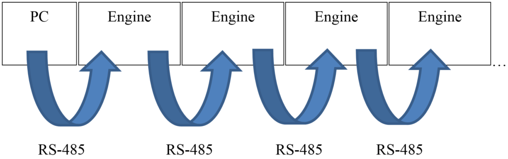
More commonly used option is to use IOFireBug Engine itself as USB-RS-485 convertor. This can be achieved by connecting IOFireBug Engine to PC using USB cable, and other Engine devices connects to main engine’s integrated RS-485 interface (Rx/Tx pins).
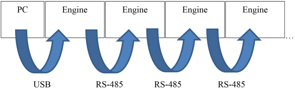
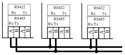
Using RS-485 interface, following wiring scheme is used:
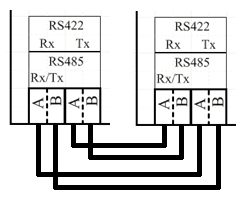
RS-422 interface
When using the RS-422 interface, this firmware version supports only one IOFireBug Engine device, because it is a point-to-point connection.
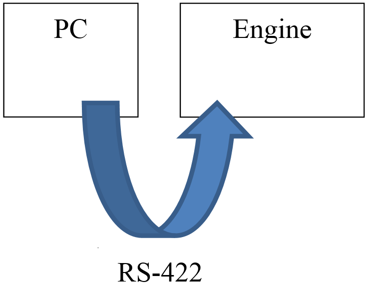
Like the RS-485 interface, it is possible to use IOFireBug Engine as RS-422 converter and connect two IOFireBug Engine devices.

Using RS-422 interface, following wiring scheme is used: