Device desription
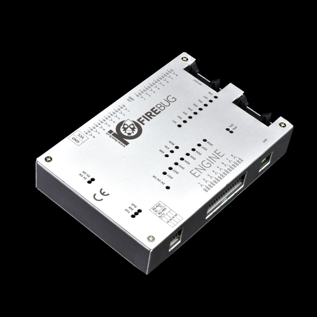
Engine board is equipped with a microcontroller and allows connection of external devices with PC. The board connects via USB (or RS-422 / RS-485) and contains following peripherals:
- 8x analog input
- 8x binary input (galvanically isolated)
- 8x switching N-FET output (galvanically isolated, all channels has common ground)
- RS-485 / RS-422 interface (configurable, galvanically isolated)
- USB to Serial interface (FTDI)
- SPI interface for expansion modules
- Power supply DC +5V for external devices (encoders, RaspBerryPi etc.)
Engine board can be extended by Wagon modules connected via SPI interface according to your application needs. SPI interface accepts up to eight wagon modules. Wagon modules can expand the main board by number of inputs or outputs depending by the type of Wagon.
Technical data
| IOFireBug Engine | |
| Producer | 4EACH s. r. o. |
| DI specification | 8x galvanically isolated binary input (by optocoupler)
Input voltage 5 – 30V |
| DO specification | 8x switching N-FET output
Max. 50V / 3 A All binary outputs are equipped by PWM function |
| AI specification | 8x analog input 12bit / 1,4MHz (ADC frequency)
Input voltage 0 – 10V |
| Integrated power supply DC 5V | 5V / 1A |
| Communication interfaces | USB (FTDI – COM port), RS-422 / RS-485, SPI |
| Input voltage | 10 – 30V DC |
| Consumption | 100mA to 500mA / 12V (depends on connected expansion modules) |
| Dimension | 140mm x 100mm (w x h) |
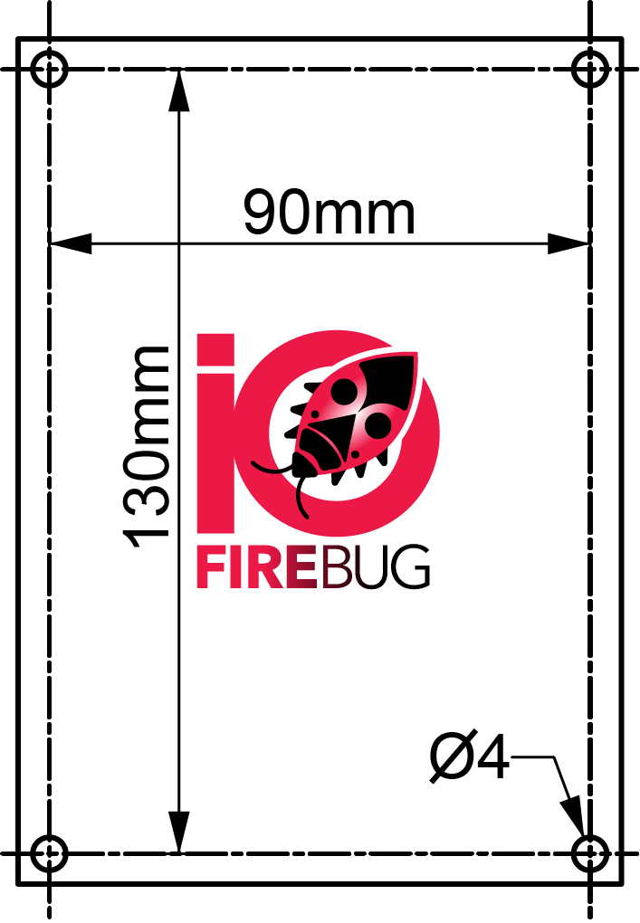
| Mounting holes dimensions | 130mm x 90mm |
| Weight | 150 g |
| Operating temperature | -20° C to 70° C |
| Voltage protections | Overvoltage, reverse polarity |
| Additional functions | Expandability by IOFireBug Wagon modules (various types)
Possibility to connect another IOFireBug Engine set by RS-422 interface Possibility to connect more IOFireBug Engine sets by RS-485 interface |
Schematic
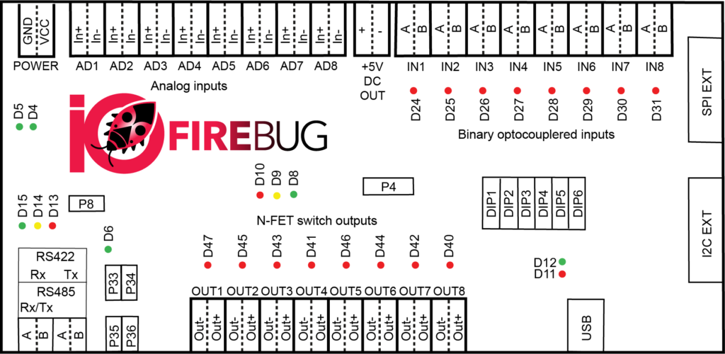
Interface
POWER – Input voltage connector
AD1 to AD8 – Analog inputs
+5V DC OUT – Power supply DC 5V
IN1 to IN8 – Binary inputs
RS422/RS485 – Serial bus for PC or IOFireBug Engine interconnection
OUT1 to OUT8 – Binary outputs
USB – PC interface (FTDI – internal USB to serial converter)
SPI – Interface for IOFireBug Wagon modules
I2C EXT – Intentionally unused
Configuration
P8 – Serial bus type switch (RS422/RS485)
P4 – System connector
DIP1 to DIP6 – Link address configuration DIP switch
P33 to P36 – Serial bus termination
States
D4 – Internal voltage 5V state
D5 – Internal voltage 3.3V state
D24 to D31 – State of each binary input
D15 (TxD) – Serial bus transmitter state
D14 – Serial bus communication direction
D13 (RxD) – Serial bus receiver state
D8 to D10 – Processor a FW state
D6 – DC – DC +5V converter state
D47, D45, D43, D41, D46, D44, D42, D40 – State of each binary output
D12 (TxD) – USB transmitter state
D11 (RxD) – USB receiver state